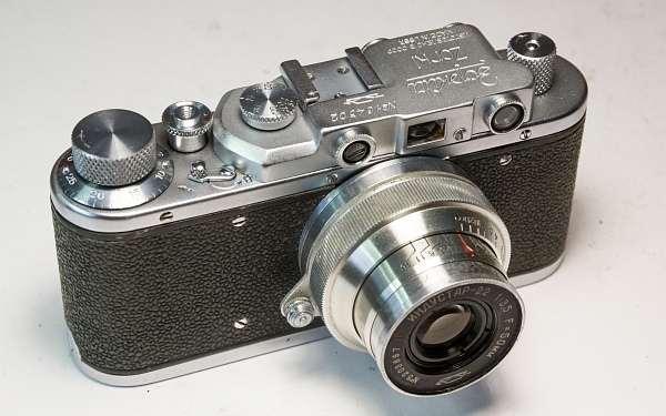
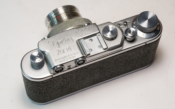
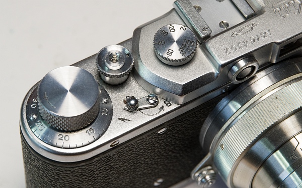
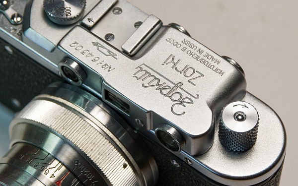
1. This is what it looks like
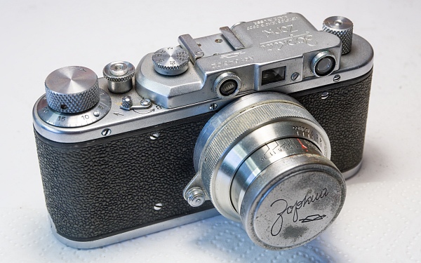
As is so often the case, the shutter clothes were dry and brittle, and it was running sluggishly. A service is therefore in order.
Considering it dates from 1952, however, it still looks in quite decent condition.
2. Remove cover
2.1. Let’s start taking it apart.
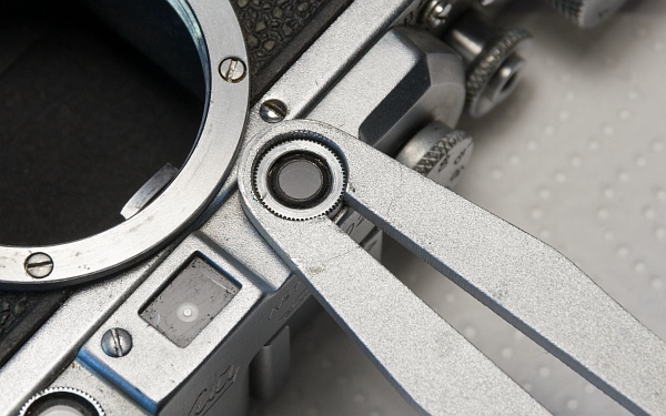
First, we remove the eyepieces using a suitable tool.
The eyepiece on the left in the picture consists of a chrome-plated ring and an adjustable lens that is screwed in separately. This lens is used to adjust the vertical offset of the rangefinder. The lens is often very tight; a tension wrench works well here.
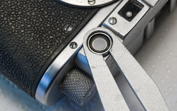
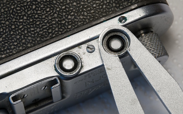
The rear eyepieces are sometimes very tight. A few drops of WD-40 and leaving them to soak overnight often work wonders (below).
You can get a tool kit like this (6 wrenches in various sizes) on eBay, for example.
2.2. Next, the top cover is removed.
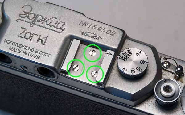
Remove the 3 screws from the accessory shoe (left).
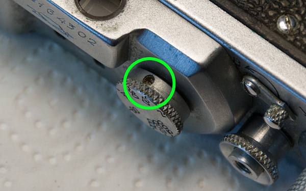
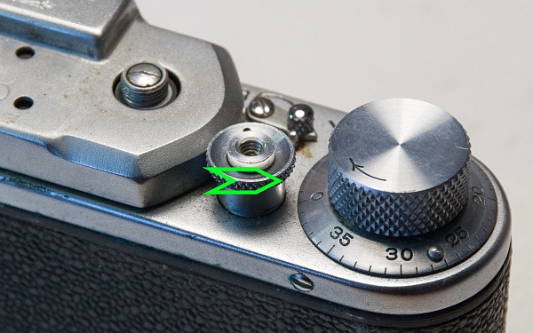
Loosen the small grub screw in the shutter speed dial and unscrew the dial anti-clockwise (bottom left).
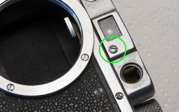
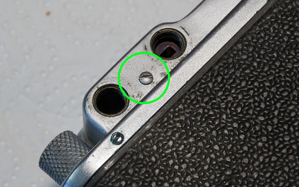
Now unscrew the two screws and remove the release button. Then remove the cover (bottom).
3. Removing the casing and parts
3.1. The lens mount and the body must be removed.
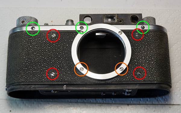
Remove the 4 screws at the front that hold the shutter (red), the two lower screws on the lens mount (orange) and the three screws marked in green on the front (left).
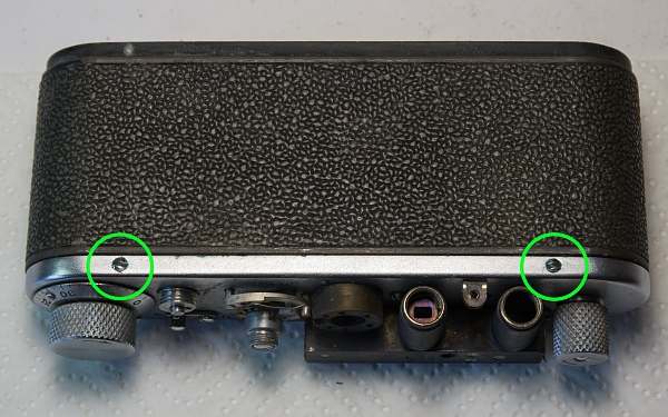
At the back, remove the two screws (bottom left).
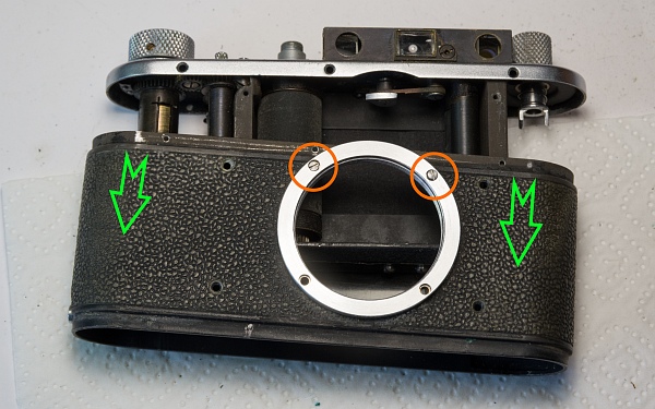
You can now slide the casing off. Next, remove the two screws marked in orange (at the bottom).
There is a threaded plate beneath each of the screws marked in orange.
Now remove the lens mount and take out the wax paper discs that are revealed. When reassembling, they must be replaced exactly as they were found.
3.2. Rewind crank and winding knob

Remove the screw and dismantle the rewind crank as described in other instructions (left).
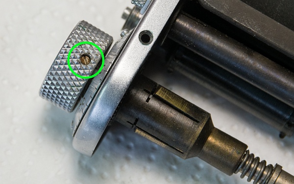
The winding knob is secured by a grub screw. Remove this and unscrew the winding knob anti-clockwise. Hold the gear wheel on the underside firmly whilst doing so, otherwise there is a risk of over-tightening a spring. The winding knob can sometimes be very tight (bottom left).
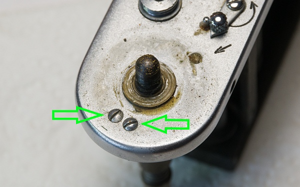
Once the film index disc and a washer have been removed, these two screws become visible. If you loosen these, the lower part of the winding knob can be removed and dismantled further (below).
3.3. The speed control components are now being dismantled.
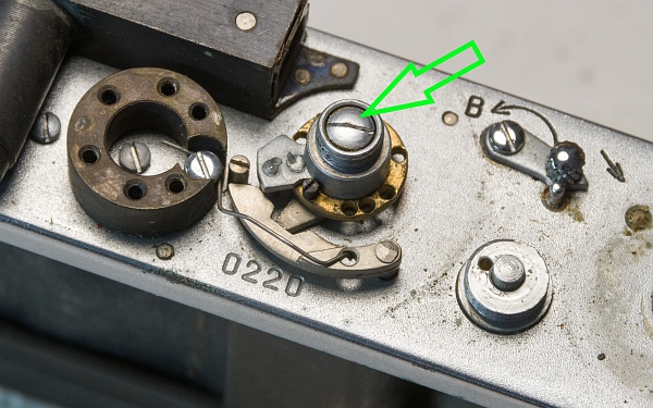
First, remove the speed-setting knob. A spring will be visible beneath the large screw. Remove the silver knob (left).
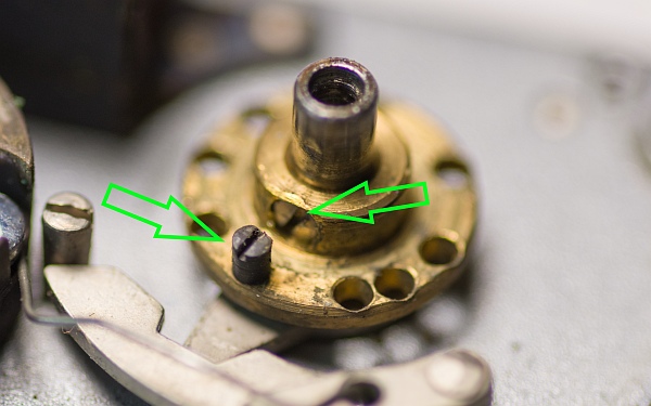
Beneath this, you can see the disc with the holes for the various times. It is held in place by a long grub screw. First, you must remove the small black locking screw, which prevents you from switching from Z to 1/500 sec. The disc itself can be very tight and may therefore sometimes need to be prised loose. (bottom left)
Now remove the spring secured by the screw and pull out the delay lever. Mark the position of the driver when the shutter is cocked (as shown), e.g. with a small scratch (below).
Sometimes (as here) there is a second number on the top plate. I do not know what purpose it serves. It is probably an internal production number.
4. Remove the shutter
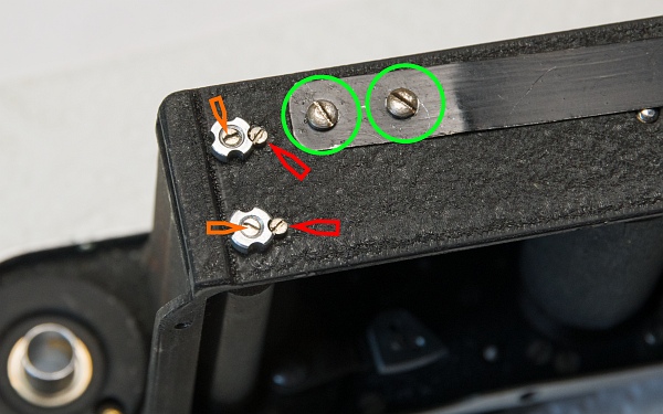
Before we can remove the shutter, the springs must be released.
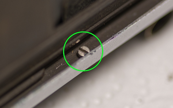
Remove the locking screws marked in red. If the nuts do not come loose, hold the screws marked in orange in place with a screwdriver and loosen the nuts clockwise using pliers (left-hand thread!). The springs must be fully released before the shutter can be removed.
When you remove the screws marked in green, the release spring and the light shield inside will come loose; you can do this now or later.
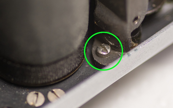
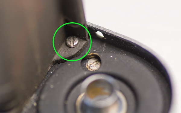
Now remove the 3 screws marked (one on the large drum, one next to the rewind handle, and one at the back in the centre).
The shutter can then be removed from the housing.
5. Remove the gears
All gears, as well as the rewind release mechanism, must now be removed.
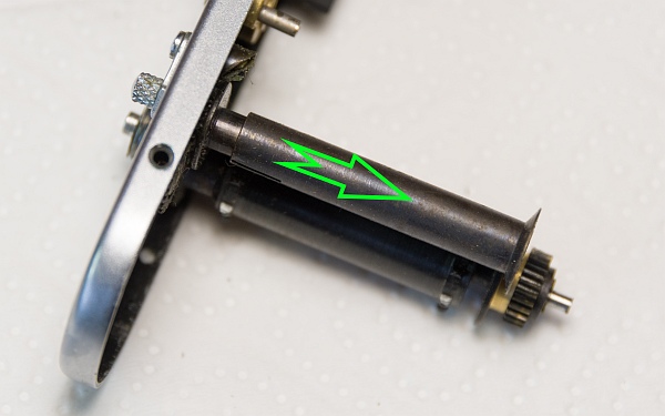
First, remove the rewind release mechanism. Pull off the sleeve (left).
Underneath, remove the screw, the spring and a small washer. The gear can then be removed (bottom left).
The spiked roller is secured with a small grub screw. Remove this (below).
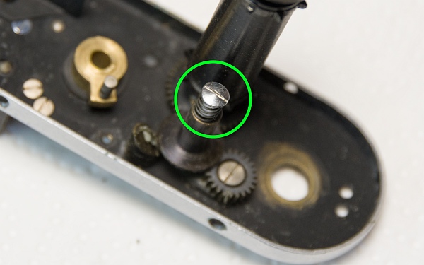
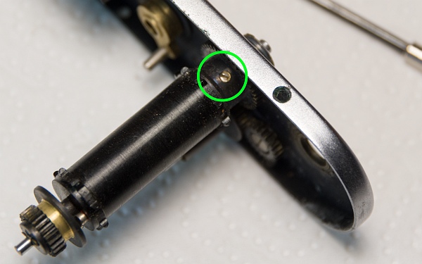
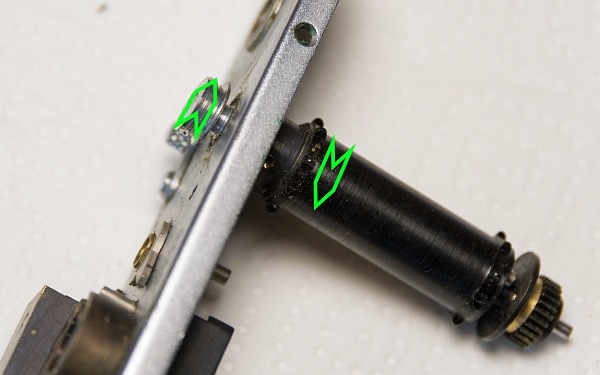
The spiked roller can now be unscrewed. It is often very tight. An eyepiece wrench or a pair of padded pliers will do the job well. The spiked roller itself consists of two parts, which can be unscrewed from one another (left-hand thread!) (left).
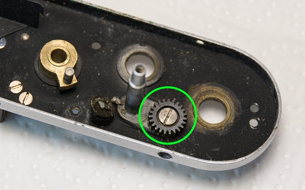
The small gear must now be unscrewed (bottom left).
Now remove the upper part of the rewind release mechanism. There are often small washers under the lever and under its counterpart on the underside. These must not be forgotten when reassembling, otherwise the lever will move too easily (below).

6. Remove the rangefinder and more parts
The rangefinder, the rangefinder arm, the upper light shield and the accessory shoe mount are now removed.
The rangefinder is held in place by five screws, one of which is hidden beneath the rangefinder arm.
This reveals the three screws on the rangefinder arm. The arm can then be removed.
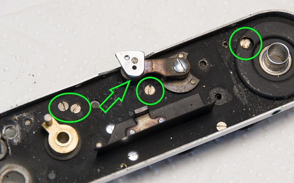
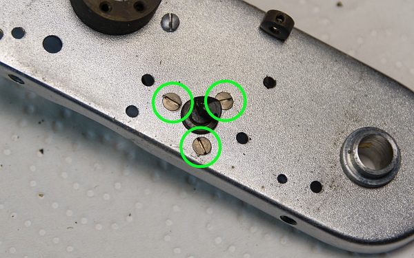
The upper light shield is held in place by two screws.
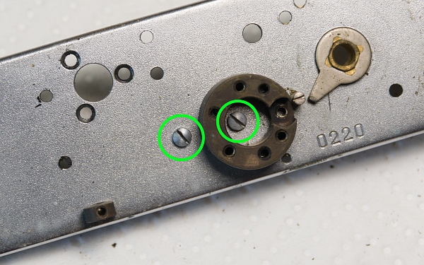
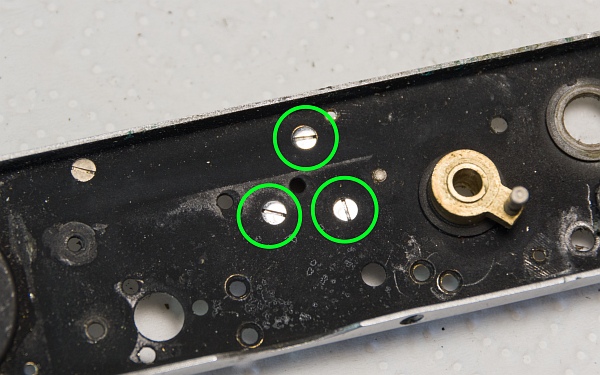
A further 3 screws are used to secure the accessory shoe (the round, dark part on the left of the picture).
7. Disassemble the shutter
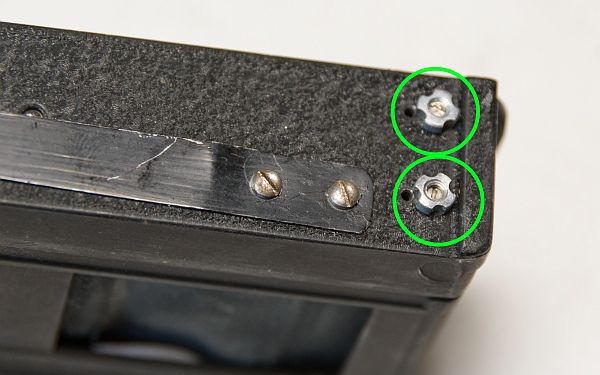
The two tension nuts are now to be removed completely (left-hand thread!).
The shutter can then be removed from the shutter box. We now remove the two pulleys and the small sleeve at the bottom.

Remove the locking screw in the gear. It restricts the movement of the gear.
Unscrew the large screw that holds the central gear in place. It may be very tight. Do not use force! If it breaks off, the camera is ruined.

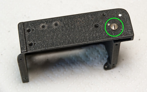
Before the old cloths can be removed, a few preparatory steps need to be taken.
Make sure you mark the end of the cloth on the large drum! The new cloth must be reattached at exactly that point.
Once the cloth has been removed, its length must be measured and noted down (plus approx. 1 cm to allow for sticking it down).

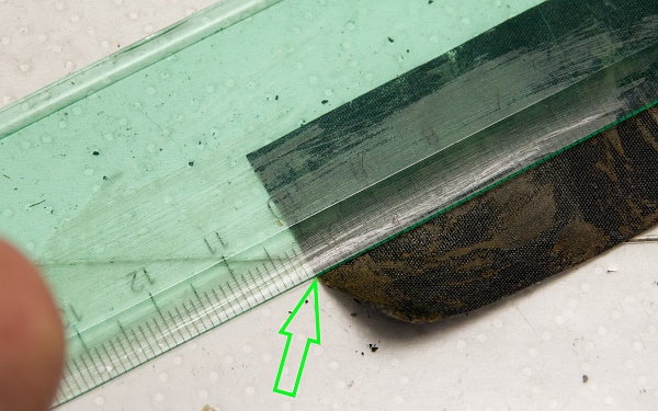
Cut the old cloths off the ribs and remove any adhesive residue from the drum and one of the sleeves.
Using a suitable tool, you can unscrew the sleeves of the tension springs. Inside them, too, there is old grease and grime that has built up over the decades.

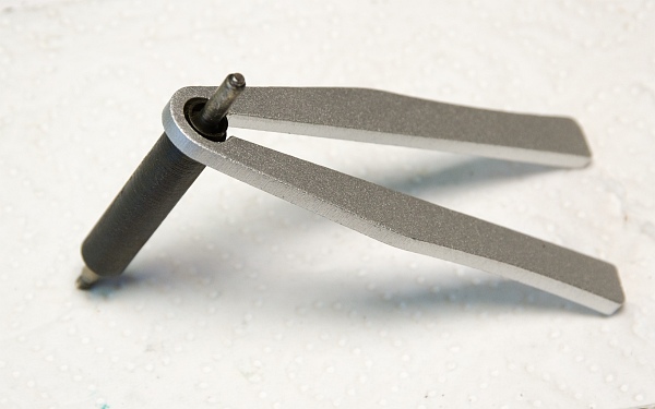
8. Dismantle the base plate
The base plate can also be dismantled further.
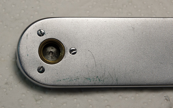
The three screws secure the tripod mount (left).
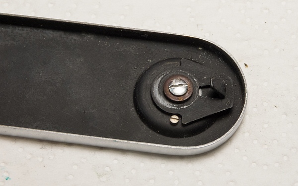
The locking mechanism is slightly more complex in design.
Once the silver screw has been removed, the thicker washer, the rotating locking hook and another washer can be removed (below).
On the underside, you will then find the locking knob.

9. An overview of all relevant parts

After cleaning, I photographed the relevant parts individually and numbered them. I’ll refer back to the numbering when reassembling.
As there are quite a lot of parts, I’ve moved them over here.
A few tips on cleaning: The best way to remove the worst of the grime that’s built up over decades from the metal parts is to use lighter fluid and a toothbrush. I then place the parts in an ultrasonic bath to remove the last traces of dirt and grease. I polish the chrome parts afterwards with polishing wool; NevrDull has served me well so far.
It’s well worth the effort. Once reassembled, a Zorki treated in this way runs as smoothly as a Leica.
So let’s start putting the jigsaw back together.
10. Assemble the rewind release and winding gears
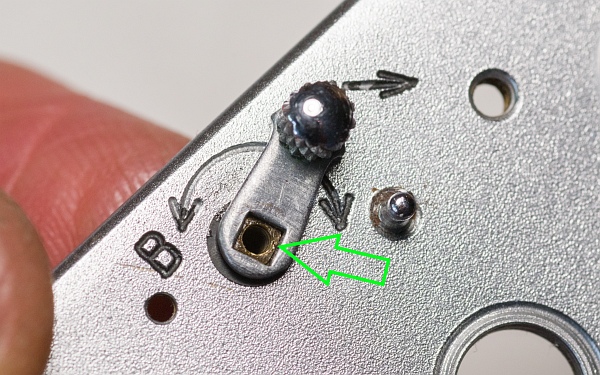
10.1. Refit the rewind release mechanism.
Insert the wedge-shaped part and any washers from Parts 16 into the hole from below. Hold the part in place and place the washer(s) on top.
Then the lever is fitted and secured with the screw. The whole thing can turn into a real test of patience...

10.2. Reassemble the tensioning mechanism.
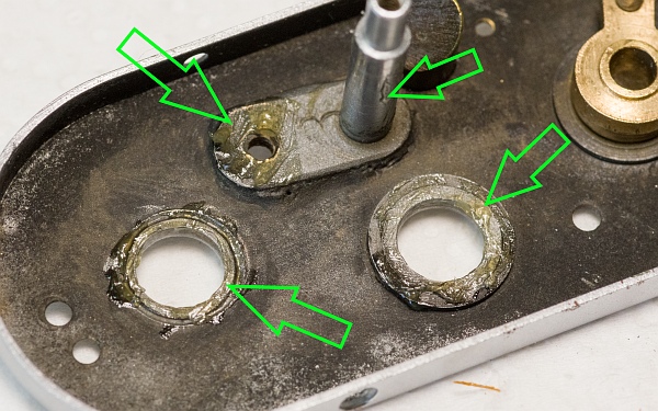
First, we lightly grease the marked areas. Less is more.
Take the spiked roller from Parts 19 and screw it on loosely (do not tighten it yet).
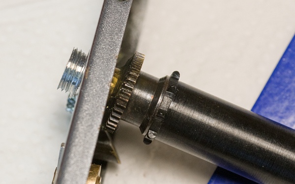
Take Parts 20 and first fit the gear, the washer and the spring onto the axle. Then secure them with the screw.
The spiked roller can now be screwed into place permanently and secured with the grub screw.
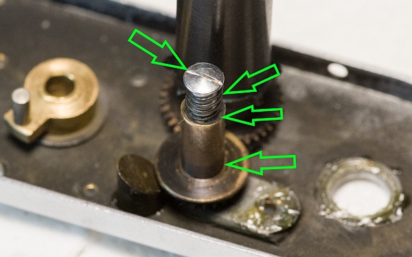

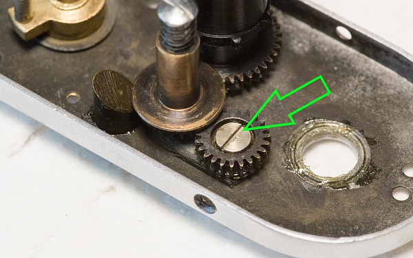
Refit the gear from Parts 9. Apply a small amount of grease between the screw and the gear.
Finally, fit the sleeve back onto the rewind release. The parts should now turn freely and easily.
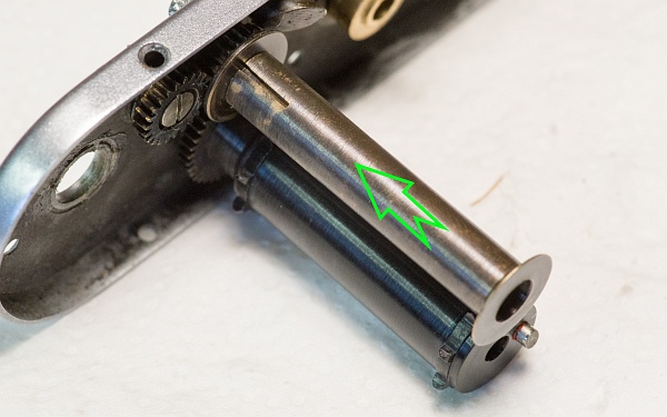
10.3. Reassemble the winding knob.
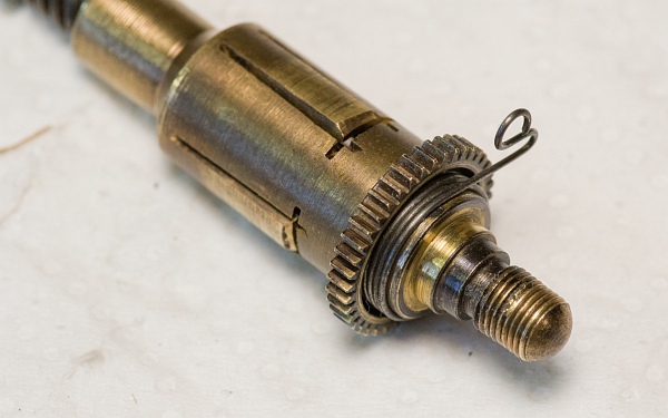
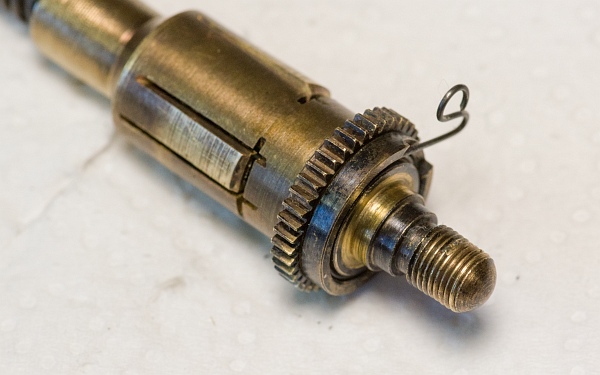
Use parts Parts 26. Slide the washers and the spring onto the threaded rod, then push it through the sleeve and screw it onto the gear.
The spring, which prevents the cocked shutter from firing accidentally, must be fitted the right way round (left).
Then slide the small ring over the spring with the notch facing upwards. The spring must sit in the recess (bottom left).
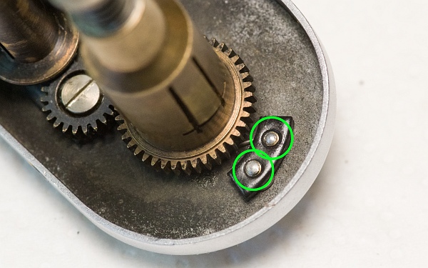
Now fit the winding knob and secure it using the small threaded plate and the two screws (below).
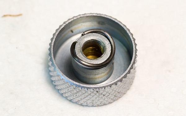
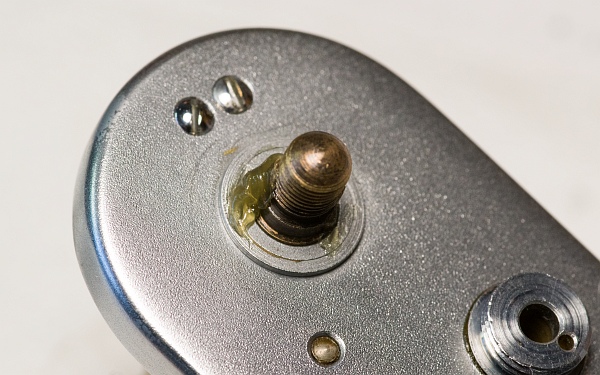
Clip the spring onto the bottom of the winding knob (bottom left). Apply a bit of grease to the axle, fit the washer with the flange facing upwards, then the film counter disc. Then screw the winding knob on and secure it with the grub screw.
Once the gears have been lightly oiled, everything should now move smoothly. The winding knob must not be able to turn back; otherwise, the spiral spring has not been fitted correctly.
11. Installing the rangefinder
Take Parts 10 and screw on the accessory shoe bracket with the opening facing to the right. Now refit the small locking screw for the delay lever and the screw bracket from Parts 11.
Refit the light trap from Parts 14 as well. This sometimes requires a bit of patience. Now we can fit the rangefinder.

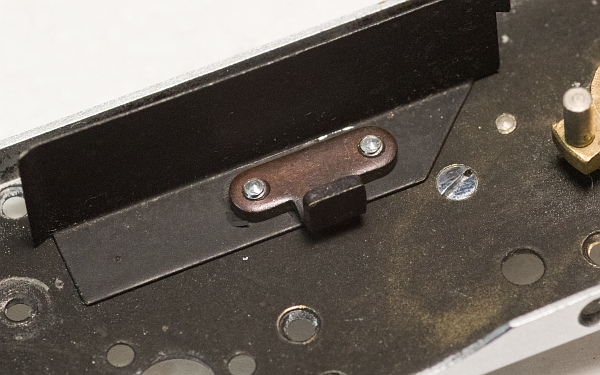
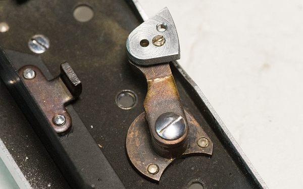
The rangefinder arm from Parts 13 is secured in the position shown using its three screws.
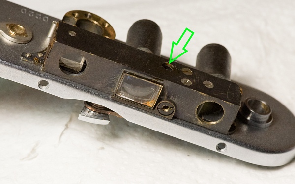
Now let’s fit the rangefinder (Parts 25) back in. Unscrew the large screw at the top of the rangefinder (sometimes there’s just a piece of cardboard stuck there) and use a small screwdriver to push the arm inside forwards. This makes it easier to fit the rangefinder back on.
12. Prepare and install the shutter
12.1. Prepare the shutter case.
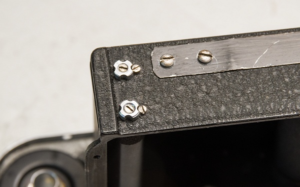
Hook the tension spring back into the upper threaded section and then screw it back into the sleeves. Apply a small amount of oil to the springs and the axle; it is sufficient to apply a bit oil using a screwdriver. Parts 1, Parts 2 and Parts 23.
A small amount of grease is applied to the large gear. Parts 15 and Parts 27.
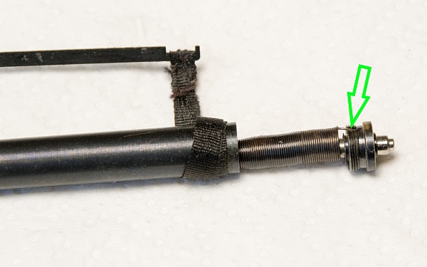
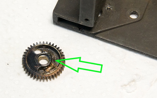
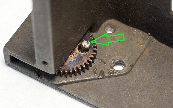
Fit the gear in place and screw the locking screw back in.
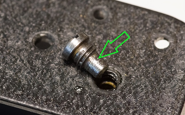
Before screwing the bolt that holds the gear in place back in, apply a bit oil to the axle.
12.2. Cut the cloth to size and stick it down.
Cut the cloths to the measurements you noted down during the dismantling process. They are usually 3 cm wide and 10 cm and 7.5 cm long. We need the following pieces here: Parts 1, Parts 23 und Parts 24.
Allow an extra 1 cm for the adhesive and stick the cloths securely around the ribs using a suitable adhesive (e.g. standard Pattex).
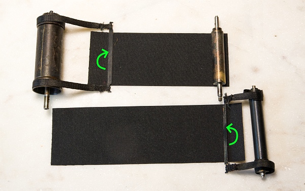
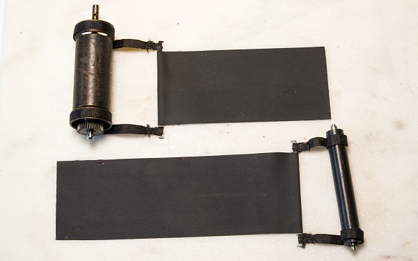
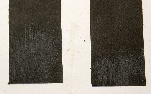
The cloths I use (eBay – nobbysparrow – I order larger pieces from there and cut them to size) have a rubberised side and a fabric side. I stick the fabric side round the ribs, whilst the rubberised side goes onto the roller or drum. To make them stick better, I roughen up the rubberised side slightly with sandpaper.
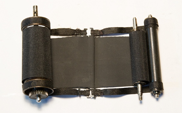
The roll of the first curtain is glued to the short strip of fabric. Make sure that the curtain rolls up neatly and straight.
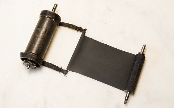
The second (long) curtain is placed over the short one (with the ties underneath the spindle) and threaded through the large drum. The curtain must now be glued to the large drum exactly at the point marked during removal.
This is what it should look like once everything has been fitted correctly.
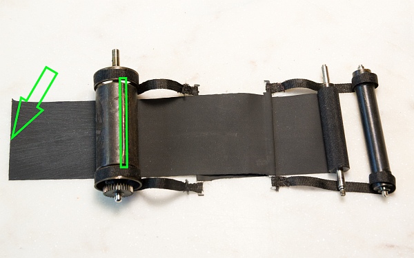
12.3. Insert the shutter into the shutter box.
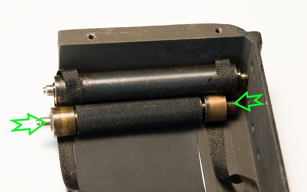
Slide the rollers onto the sleeve of the first curtain (both rollers are identical) and don’t forget to fit the small spacer (siehe Parts 1 left) onto the bottom of the axle. Then insert the axles through the corresponding holes in the base of the shutter box and secure them with the clamping nuts from Parts 7.
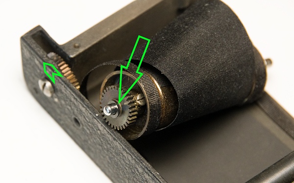
Slide any washers that may be present back onto the drum shaft; a small drop of oil on the shaft won’t do any harm either. The gear on the left in the picture must be turned clockwise as far as it will go.
12.4. Refit the shutter.
Secure the driver to the top of the camera at the point you marked during removal using a small piece of adhesive tape, so that it does not slip out of place during refitting.
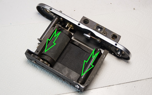
The large drum is now inserted into the shutter box so that the hole at the top of the drum is in the same position as the pin on the driver (see arrows).
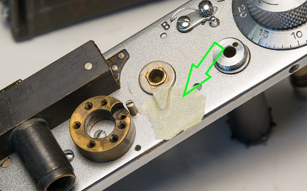
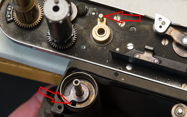
Now insert the shutter from below, holding the drum firmly in place so that it does not slip. The pin on the driver must now click into the hole in the drum, whilst at the same time the release rod must click into the hole in the base. Once this is in place, secure the shutter with a screw.
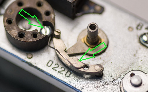
The two rollers must now be fitted into the existing holes with the pins at the top. Only then can we insert the last two locking screws. (See arrows).
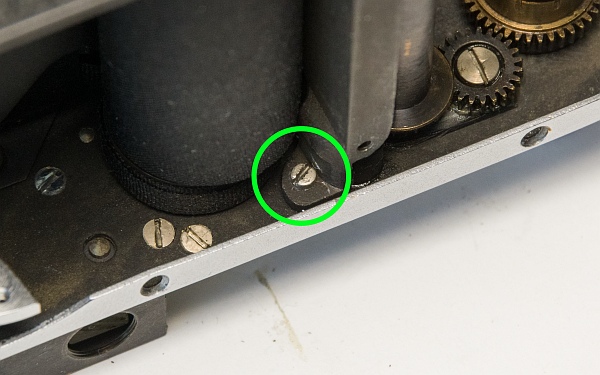
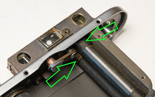
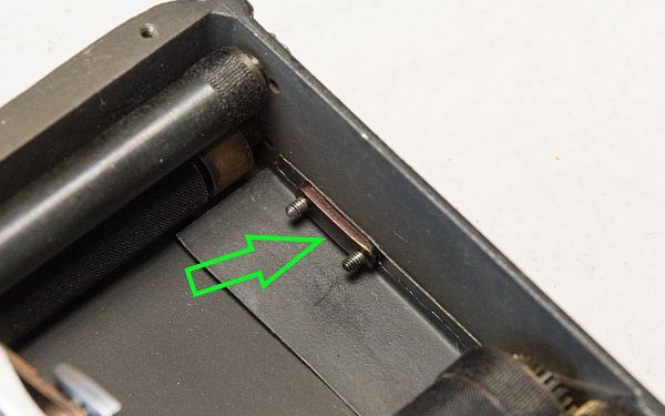
Once the shutter has been successfully fitted, the final step is to refit the lower light trap and the release spring. Parts 21 are required for this. This, too, is quite a fiddly job.
13. Install speed control
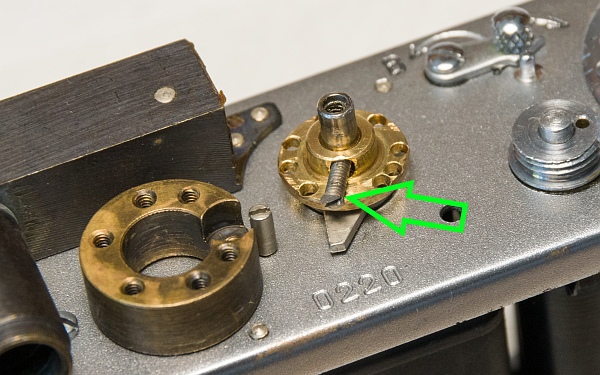
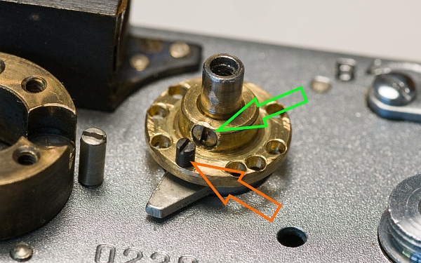
Use Parts 18 for the speed control. First, fit the brass speed disc back onto the shaft and secure it with the long grub screw (left).
Then screw the small black locking screw back in. This prevents the speed from being changed between Z and 1/500 sec (bottom left).
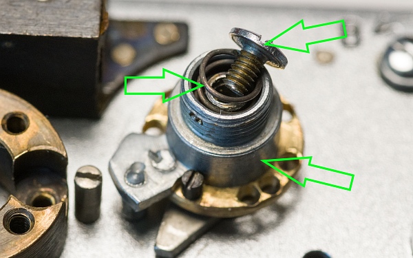
Now place the silver knob onto the shaft, insert the spring and secure it with the screw. Make sure that the spring is not pinched by the screw (below).
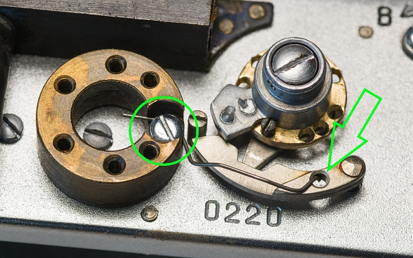
Now secure the spring to the accessory shoe bracket with the screw, insert the delay lever (it must fit into a hole at the very bottom, which can be quite fiddly) and position the spring in the hole as shown (bottom left).
The tension springs can now be wound anti-clockwise. To begin with, try 4 turns for the first curtain (top screw) and 3 for the second curtain. Secure the tension nuts with the small locking screws (at the very bottom).
Lightly oil the gears at the bottom and test the mechanism by cocking and releasing the shutter. Now adjust the tension of the shutter springs so that the shutter operates accurately.
14. Assemble the housing
14.1. Fit the rewind crank.
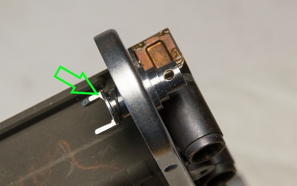
We need Parts 17. Place the washer onto the fork, put the spring on top, and then slide the fork through the opening (left).
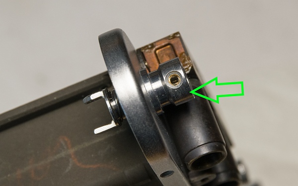
Next, fit the ring, with the bevelled side facing downwards (bottom left).
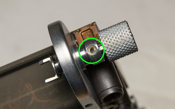
Now fit the knob and secure it with the screw (bottom).
14.2. Secure the body.
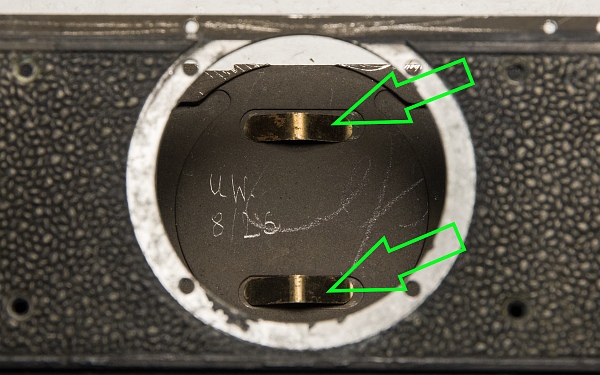
We’ll use Parts 31. Place the two springs into the recesses (left).
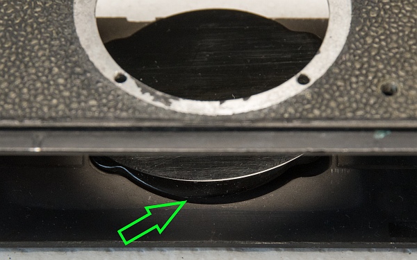
Then place the film pressure plate on top, with the bevelled side facing downwards. Make sure the springs do not slip out of place (bottom left).
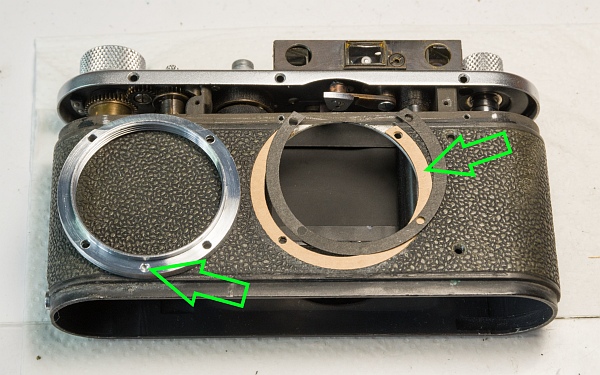
Now place the shims (the strips of cardboard or wax paper) back exactly as you removed them.
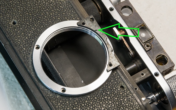
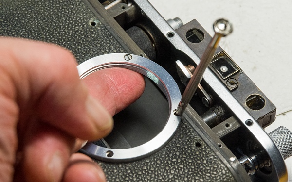
The screw-on mount can then be carefully fitted without displacing the shims. The milled recess must be at the bottom; otherwise, the distance mark on the lens will not be at the top once the lens is screwed on (below).
Position the upper threaded plate in this position from the inside and screw it into place (bottom).
Then slide the housing onto the camera and tighten all the housing screws (Parts 8).
14.3. Fit the cover and other parts.
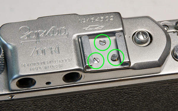
Place the top cover on and secure the accessory shoe to the top using the 3 flat-head screws (Parts 4).
Now screw the rear eyepieces back into place (Parts 3). The clear glass piece is screwed in on the left. It is sufficient to tighten the eyepieces by hand until they are snug.

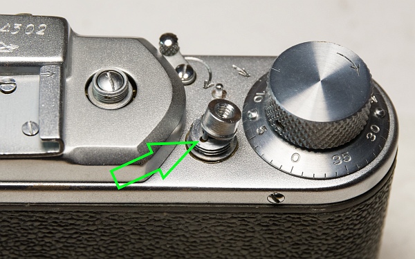
Insert the trigger button with the small pin into the hole and screw the collar onto it (Parts 6). Now screw the speed dial from Parts 5 back on and secure it with the grub screw. Don’t forget to use washers if necessary.
Don’t forget to refit the base cover (Parts 29).
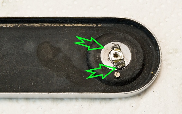
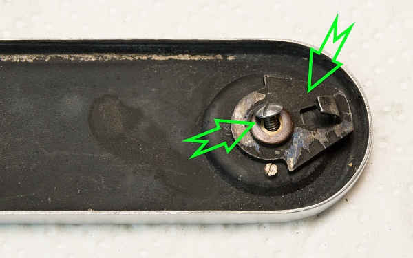
First, push the knob through from below.

Place the washer(s) on top and apply a little grease so that the locking knob turns easily.
Then fit the locking plate and the smaller washer, and secure both with the screw.
14.4. Adjust the rangefinder.
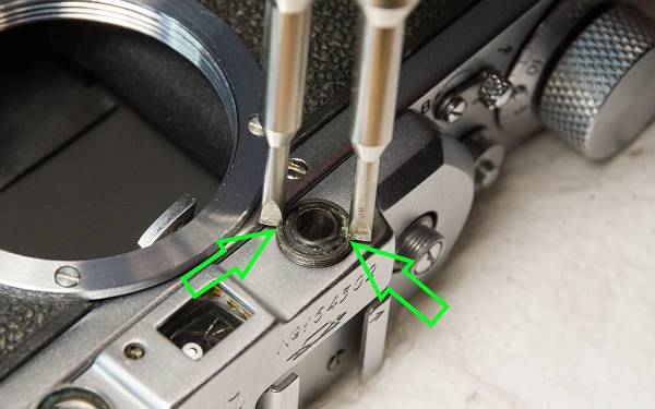
Screw the two front eyepieces in. The right-hand one must be tightened securely using a spanner. It contains an adjustable lens.
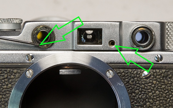
The rangefinder can be adjusted in two ways. To adjust the vertical offset, turn the lens on the left-hand side of the image. Turning it anti-clockwise moves the double image in the rangefinder further down.
The horizontal offset is adjusted using the small screw on the right-hand side of the image. Turning it clockwise moves the double image towards infinity.
15. Lens
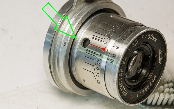
Service of the lens will be described here.
16. Result
All that effort was really worth it! The camera looks almost as good as new, is perfectly adjusted and works very well.