
Rollers and tension spring for the first curtain. The curtain is glued to the large sleeve, whilst the tapes of the second curtain run over the small rollers.
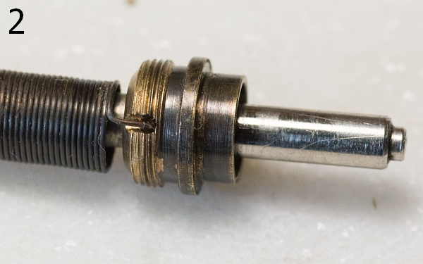
The tension spring is hooked in at the top, and both are then screwed into the sleeve. Before fitting, the two rollers are then fitted over the axle at the top and bottom. The small spacer on the far left of the top picture is fitted over the axle at the bottom.
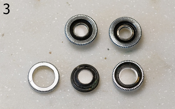
The four eyepieces: the rear ones at the top, the front ones at the bottom. At the bottom centre is the eyepiece used to adjust the vertical offset of the rangefinder.
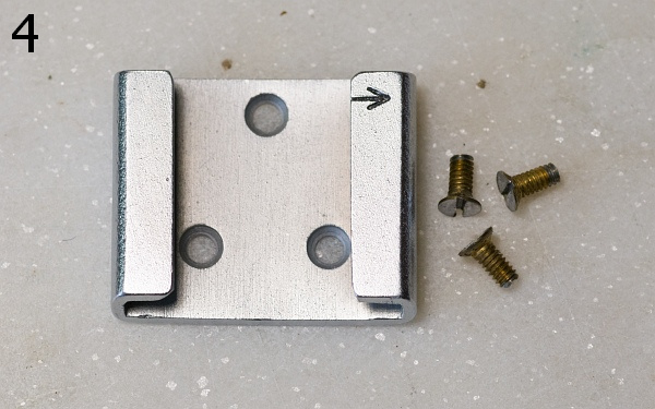
The accessory shoe and its three flat-head screws.
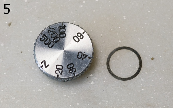
On early Zorkis, the speed dial is held in place by a grub screw and must be unscrewed; on later models, it is held in place by two grub screws and can then be removed. Sometimes there is a washer included.
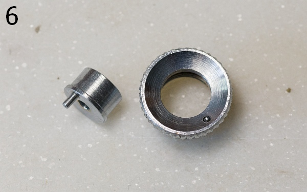
The release button and the collar around it.
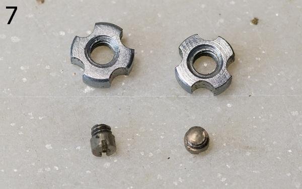
The tension nuts on the locking springs and their fixing screws. The tension nuts have left-hand threads!
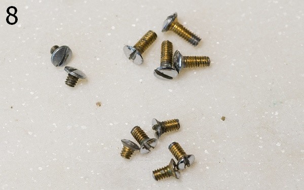
All the case screws. The four larger ones at the top secure the shutter from the front, whilst the five at the bottom secure the case. The shorter one goes at the back on the left. On the left of the picture are the two screws that hold the cover in place.
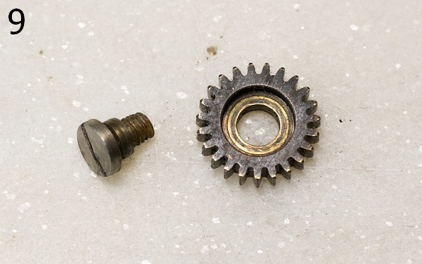
The small gear in the gearbox. A bit of grease is needed between the screw and the gear.
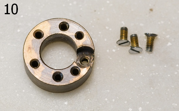
This part holds the accessory shoe and the spring for the delay lever.
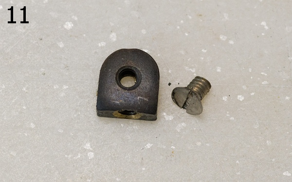
The threaded plate for the rear screw on the cover.
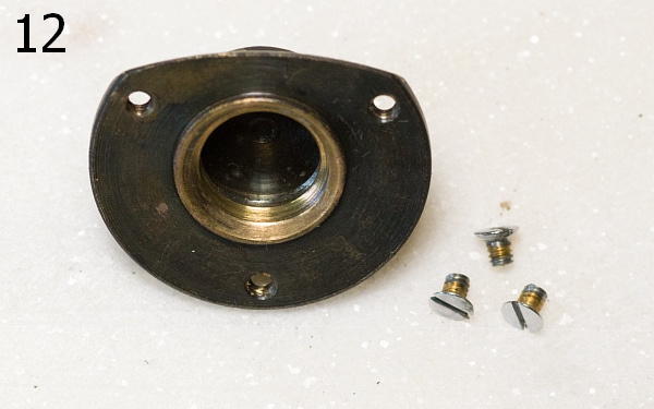
The tripod mount is secured to the base plate with three screws.
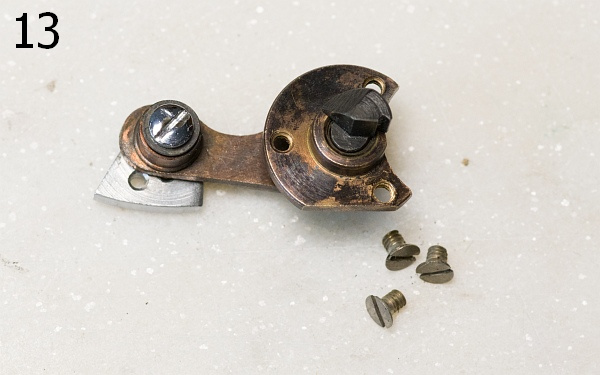
The rangefinder arm is also secured with three screws. The screw on the left in the picture is used to adjust the lever that interacts with the lens.
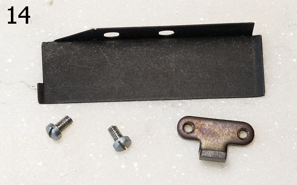
The upper light trap. Before it can be secured, part 10 must be fitted, as it partially covers its screws.
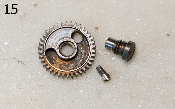
The central gear wheel with the cut-out for the shutter mechanism. The small screw limits the travel of the mechanism, whilst the large screw holds the gear wheel in place within the shutter housing. It may be very tight – do not use force! If it snaps off whilst you are unscrewing it, the camera will be nothing more than a decorative item.
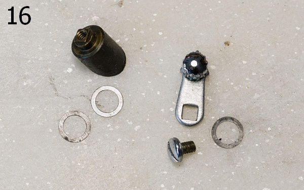
The parts of the rewind release mechanism on the top. The number and position of the washers are important during installation. Otherwise, the lever will be too stiff or too loose.
The wedge-shaped part at the top left moves the gear with the long sleeve (see 20) so that the film can be rewound.
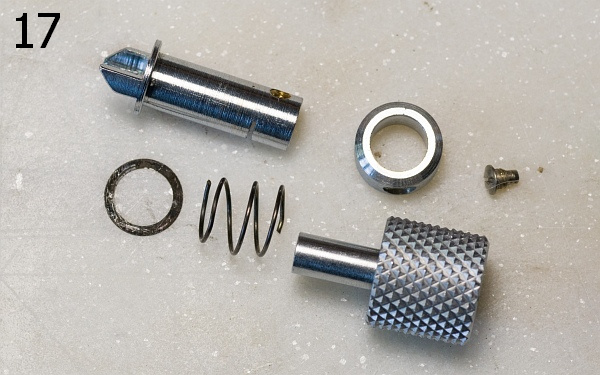
All the parts of the rewind crank. The small washer on the left is needed to prevent the spring from slipping over the fork.
The silver ring has one bevelled side. This must face downwards during fitting, otherwise the screw will not fit properly.
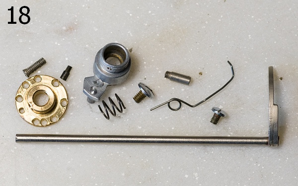
All the parts of the speed control. Holes have been drilled into the brass disc, into which the pin of the silver knob clicks into place.
The long grub screw used to secure the brass disc is a bit of a nuisance. Sometimes it slides back in very easily, and other times it turns into a test of patience.
The delay lever and its spring. Fitting it is often a nuisance too, as it has to be inserted into a hole at the bottom of the case back.
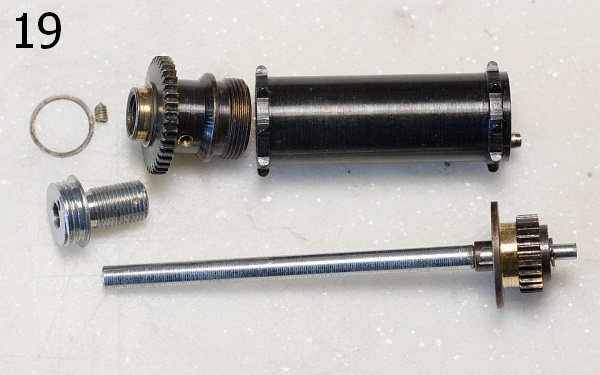
Spiked roller and release gear. The spiked roller is bolted to the cover plate from above and below and then secured with the grub screw. The rod with the gear is inserted into the spiked roller when the lock is fitted.
The spiked roller itself can also be unscrewed (left-hand thread!).
Upon release, the rod is pressed downwards, releasing the locked shutter, which can now run down.
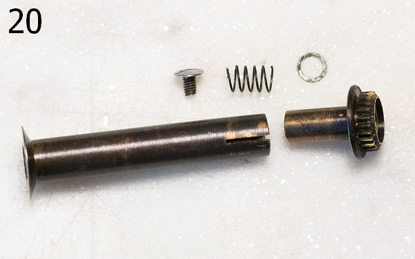
The lower parts of the rewind release mechanism. If you move the lever shown in figure 16 towards "B", the gear is raised. This disengages the gear mechanism, allowing the film to be rewound.
The spring ensures that the gear is pushed back into the gear mechanism when you return the lever shown in figure 16 to its original position.
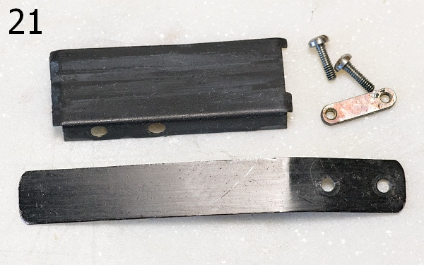
Lower light trap and release spring. Screwing the light trap back on can be quite a fiddly job.
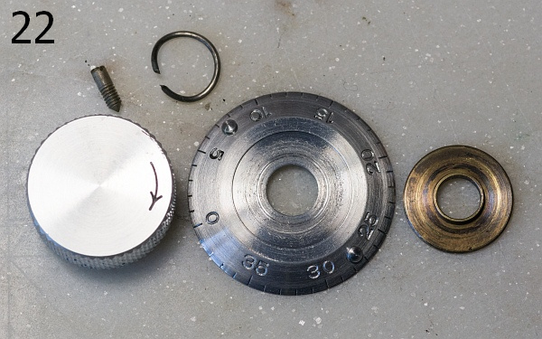
The upper parts of the winding knob. The small round spring clips onto the bottom of the winding knob. It acts as a brake on the film counter disc. Lightly grease the washer before fitting.
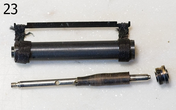
Sleeve and tension spring for the second curtain. The tension springs differ in design. There are two holes in the shaft through which the spring can be secured. For the second curtain, the spring is secured in the upper position. The springs must not be mixed up!
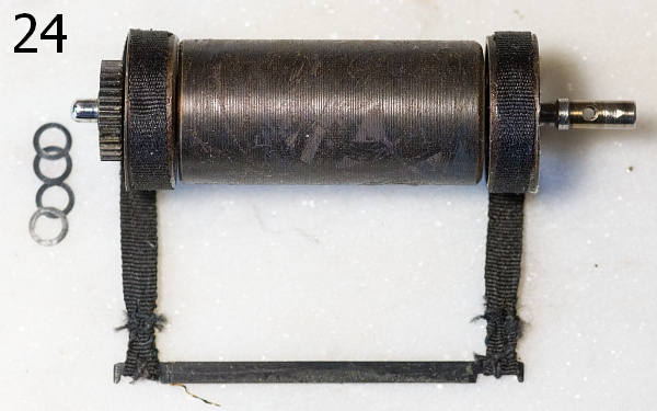
The large drum. The first curtain is attached to the crossbar, whilst the longer piece of cloth from the second curtain is stuck to the drum. There are almost always several small washers around the axle.
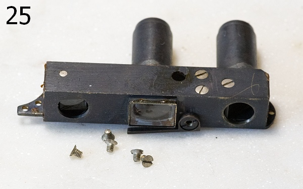
The rangefinder. It is held in place by five screws. You should not take it any further apart, as it is almost impossible to put it back together again.
There are cover plates on the right and left. If you remove the right-hand cover plate, you can take out the small vapour-coated disc of the rangefinder spot and clean it carefully, if necessary. But be careful – the coating comes off very easily! Once it’s removed, the double image in the rangefinder viewfinder will disappear.
To the left, beneath the cover plate, there are small adjustment screws for adjusting the small prism on the left.
The function of the movable lever beneath the viewfinder window in the centre has remained a mystery to me so far.
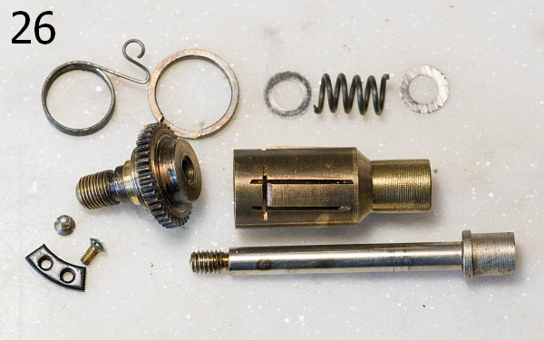
All parts of the winding mechanism. The spring at the top left prevents the wound shutter from unwinding automatically. The ring to the right of it has a recess into which the arm of the spring must fit. The holes in the threaded plate at the bottom left align precisely with the two eyelets on the spring during installation.
The winding knob is screwed onto the top of the gear wheel in the centre left. The large sleeve holds the film take-up spool. If the spool is too loose or too tight, the clamping pressure can be adjusted by carefully bending the three tabs.
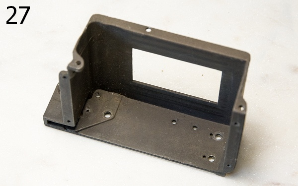
The shutter box from the inside. You can clearly see the rather large number of holes and threads.
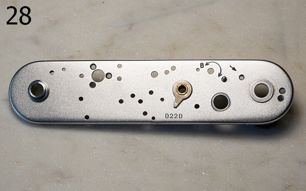
The cover plate. Only the driver in the centre has not been removed. Here, too, there is a considerable number of holes.
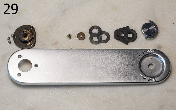
The disassembled base plate. On the left is the tripod mount (12), and on the right are the parts of the locking mechanism.
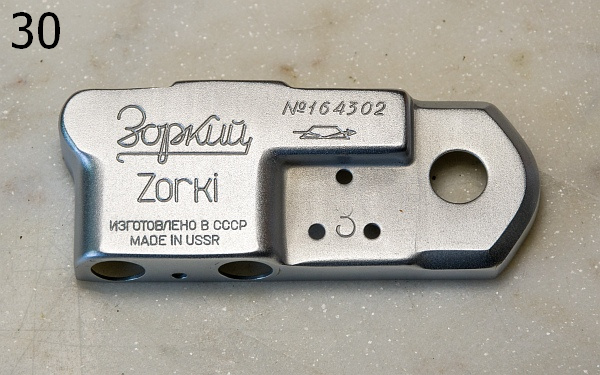
The cover with the engraved serial number and the name engraved twice. On the export versions, the name was engraved in both Cyrillic and Latin script.
It is said that the export versions are of better quality, but given the usual variations in quality in Soviet production, I am rather sceptical about that. There are export versions that run poorly and domestic versions that run superbly.
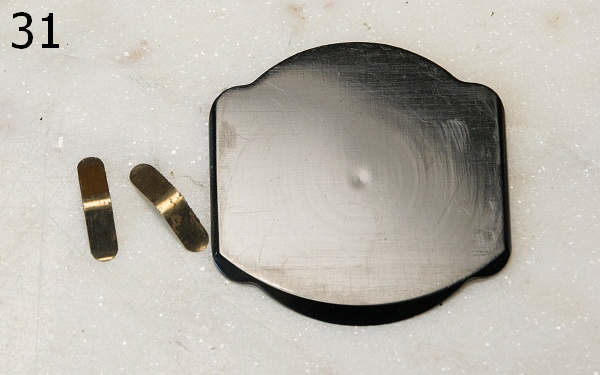
The film pressure plate and the associated springs.
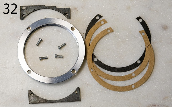
The screw mount with the fixing screws and threaded plates. It is essential that the wax paper strips are positioned correctly again.
A quick tip when tightening the screws: use a finger to prevent the screwdriver from slipping inwards. My screwdriver has slipped before and ended up in the shutter cloth...
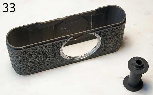
Camera body and film take-up spool. Unfortunately, the film take-up spool is missing from many cameras.