1. Disassembly
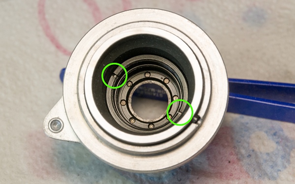
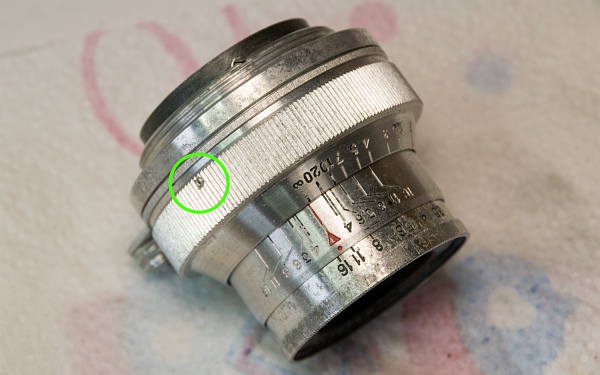
1.1. Remove the focus ring, lenses, and aperture scale.
The chrome on the lens is no longer quite as attractive, but the lenses themselves are in perfect condition and show no scratches, cleaning marks or glass mould.
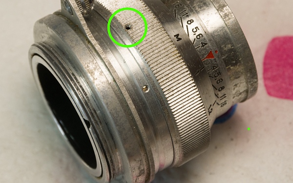
Remove the three small grub screws that hold the focus ring in place. Take care – the screws are really tiny and quite soft. If the head is damaged, the only solution is to drill it out with a Dremel. The focus ring can then be pulled off.
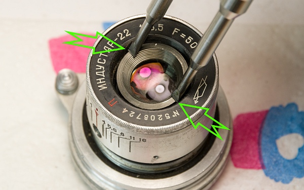
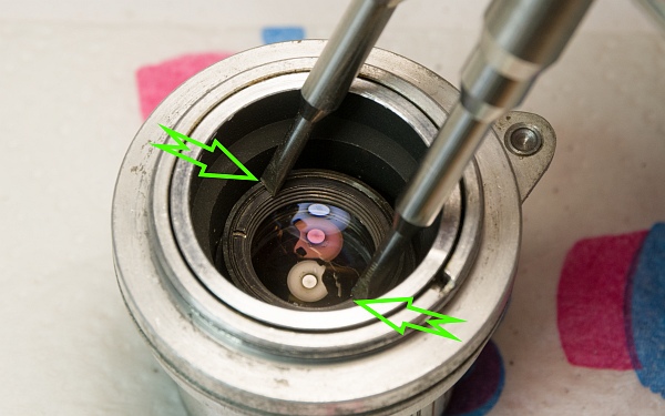
As we’ll also be cleaning the lenses whilst we’re at it, we’ll first remove the ring that holds the front lens in place using a spanner (see green arrows).
Remove the light trap and then unscrew the rear lens block using a spanner (bottom left).
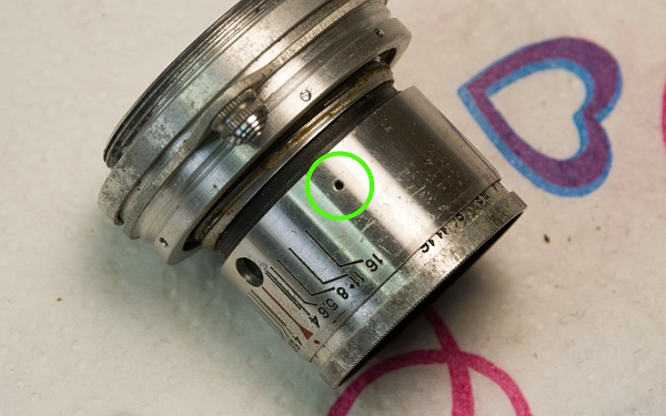
The aperture scale is held in place by three small grub screws. These must be removed so that we can access a concealed screw (below).
1.2. Remove the aperture blade housing.
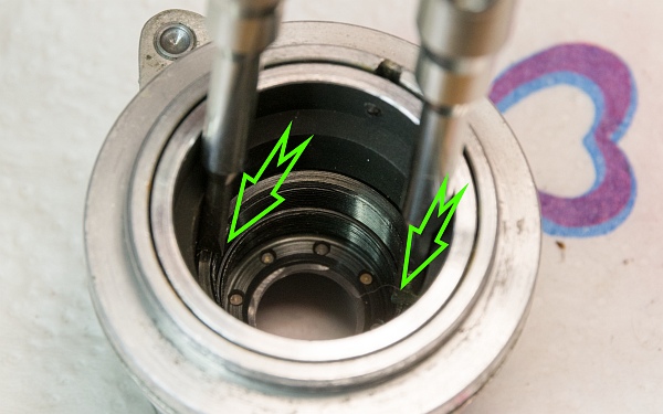
Now remove the inner ring using a spanner (left). It holds the housing with the aperture blades in place. The ring may be quite tight.
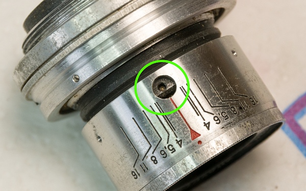
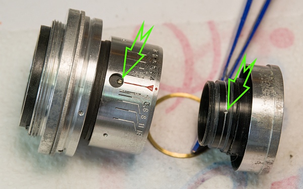
This grub screw must now be removed. It secures the aperture blade housing in the correct position (bottom left). To do this, turn the loosened aperture ring until the grub screw becomes visible.
The three parts can now be separated. Often, one or more shims are fitted at the rear of the aperture blade housing.
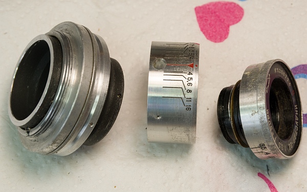
1.3. Take the focus screw apart.
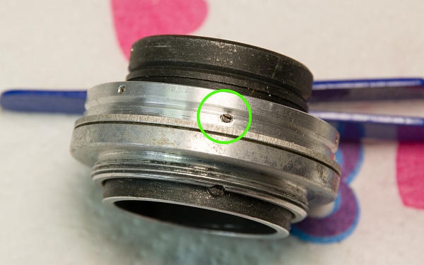
Now we need to dismantle the double focus screw. There are a few things to bear in mind here. First, set the lens to infinity.
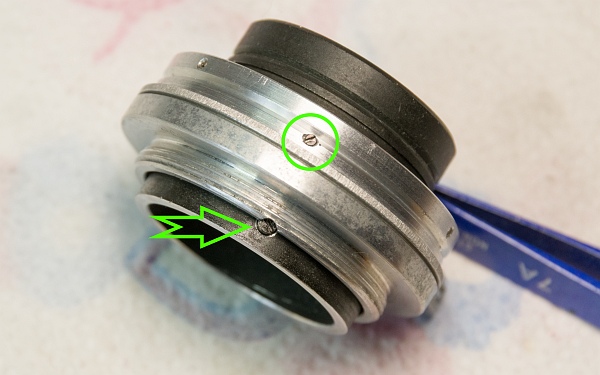
Start by removing this locking screw. It limits the focus travel (left).
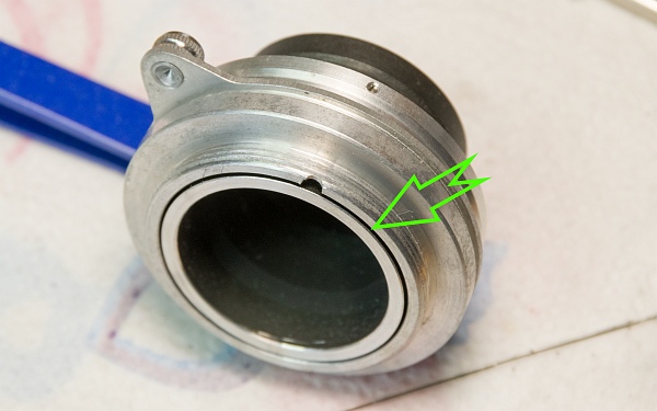
Next, remove the three grub screws that hold the cover with the focus lever in place over the focus travel (bottom left).
Important! Mark the left-hand end of the focus travel (below) on the black ring of the outer focus screw (see arrow). Unfortunately, the mark is hard to see here; I’ve made a small scratch there. The lower locking screw should be roughly in line with this mark.
The markings we make during disassembly are so important because each focus screw has several entry points. With three entry points per screw, there would be as many as nine different ways to reassemble it – but only one is correct!
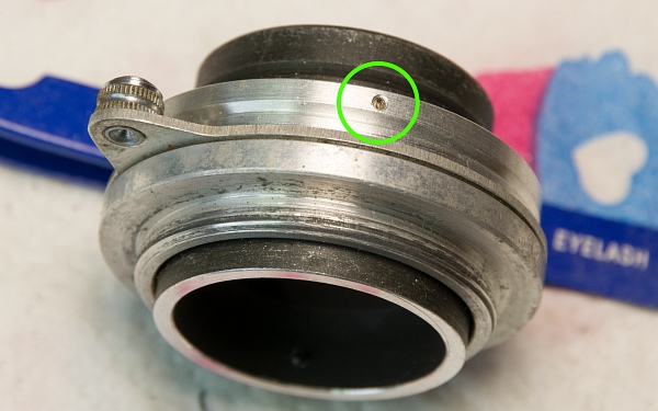
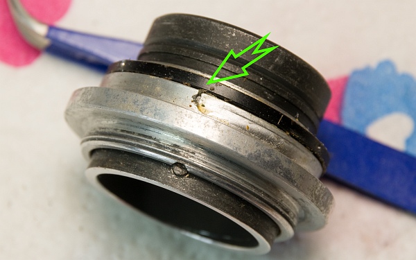
Now continue turning the outer focus ring towards infinity until the lower locking screw is fully visible outside the notch. Then remove the black locking screw.
Now unscrew the outer focus ring anti-clockwise. Important! Mark the point where the ring comes out. I used the left-hand end of the focus travel as a reference point again and marked it with two small scratches.
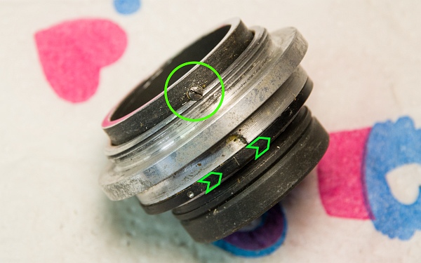
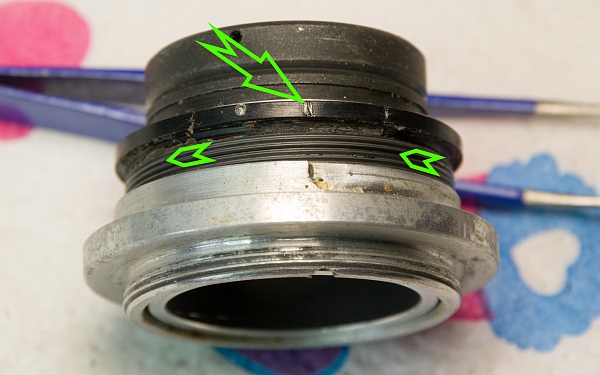
Here, the point (indicated by the arrows) where the focus screw emerges from the outer silver thread is highlighted once again.
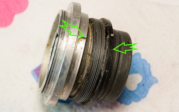
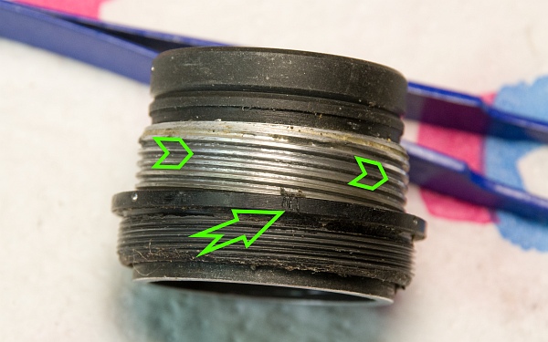
Now unscrew the outer black focus ring from the inner silver ring in a clockwise direction. Important! Here, too, it is essential to mark the point where the black ring comes out of the silver one. I have made three small scratches here. The ring came out at the position of the locking screw (hidden here).
2. Cleaning
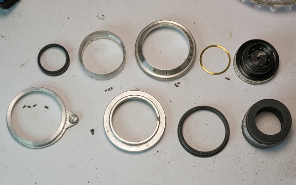
All parts have now been stripped of the old grease. The worst of the dirt can be removed very effectively using a toothbrush and white spirit; afterwards, all parts (except for the aperture blade housing) can be placed in an ultrasonic bath (left).
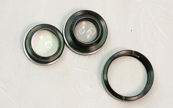
At the bottom left are the cleaned lenses, together with the front lens mounting ring.
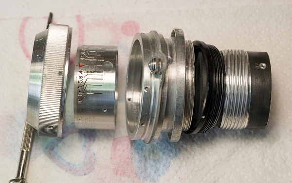
Below are all the cleaned parts in the order in which they belong together (from left to right): distance scale, aperture scale, ring with focusing lever, outer ring with M39 thread, outer focusing gear, inner focusing gear.
3. Lubrication and assembly
3.1. Assemble the focus screw.
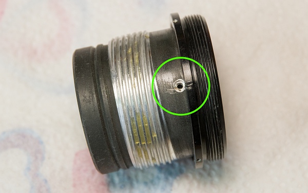
Apply a small amount of grease to the inner focus thread and turn the black focus thread – with the marked section (3 scratches) – upwards (to the left) to the position of the locking screw.
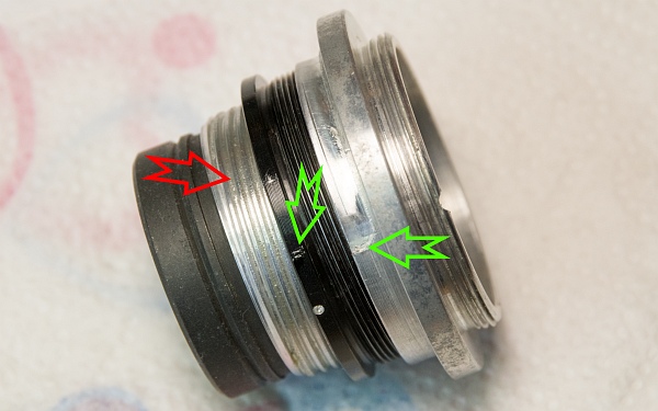
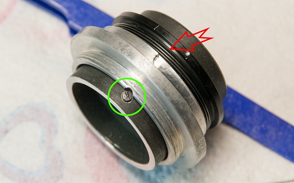
Next, screw the M39 focus ring back in at the marked spot (2 scratches). However, I made a mistake there (red arrow)! The black focus thread must be screwed in much further than shown, namely to the position from which it was removed when the lens is set to infinity (bottom left).
The bottom picture shows the correct position of the black focus thread at the top end once it has been screwed in. I then screwed the locking screw back in. As I realised later, the silver focus ring was not yet in the correct position either (red arrow). So the locking screw had to be removed again first...
But we can start by applying a bit of grease to the recess in the focus path.
Whilst assembling it at the marked point, where there was a scratch, I then realised that the silver focusing ring needs to be turned in even further (red arrow) so that you can actually screw the locking screw in. It really is quite a fiddly business.
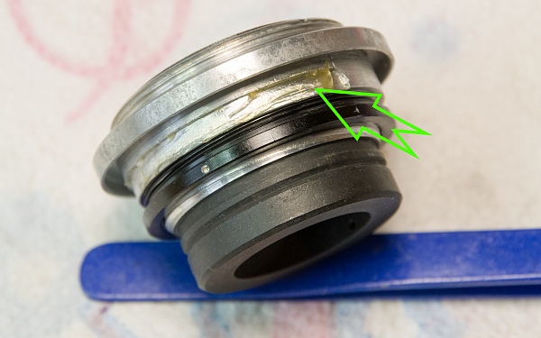
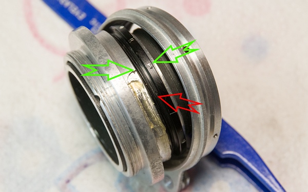
This is now the correct position. When the lens is set to infinity, the locking screw is half-covered, just as it was during removal (arrow). We now replace the silver cover and screw the small focus locking screw back in (circle). It must not be screwed in too far (otherwise you will no longer be able to focus), but nor too little (otherwise the screw will pop out of the focus path).
The correct position of the focus ring when the lens is set to its minimum focusing distance. The M39 screw thread and the silver ring must be at the same level for the rangefinder to work correctly (arrow).
3.2. Reassemble the housing.
Replace the shim(s) on the aperture housing from the rear, position the aperture scale back over the focusing unit, and secure both in place again with the grub screw. Pay attention to the markings!
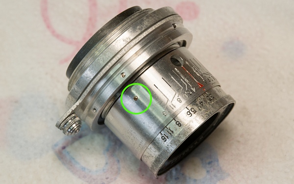
The aperture scale is then secured again using the three grub screws.
Now screw the mounting ring back onto the aperture housing and reinsert the rear lens and the front lens using the spanner.
Now all that’s missing is the meter scale and the light trap at the back. Done!