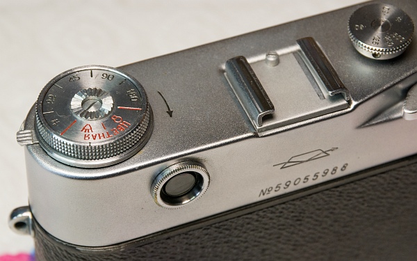
1. Remove top cover
1.1. Remove the eyepieces.
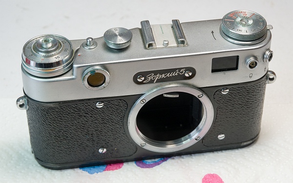
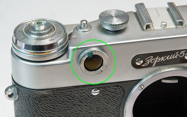
Apart from a little verdigris, it actually looks pretty good (left).
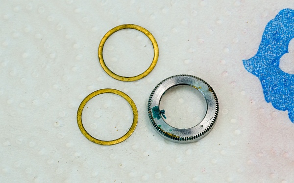
First, unscrew the ring from the front eyepiece. Surprisingly, there are two washers underneath (below).
Use a spanner to unscrew the eyepiece to adjust the vertical offset (bottom left).
Now unscrew the eyepiece from the back (bottom).
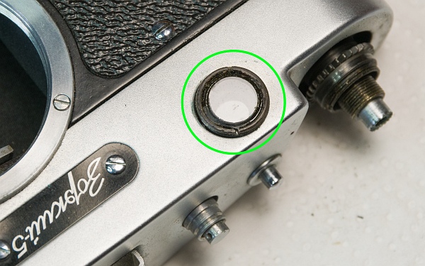

1.2. Remove the rewind crank, diopter adjustment, and other parts.
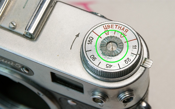
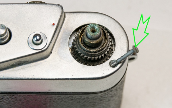
Remove the screw and take out the film index disc and the spring washer. Now hold the fork in place on the inside with pliers and unscrew the rewind crank (left and bottom left).
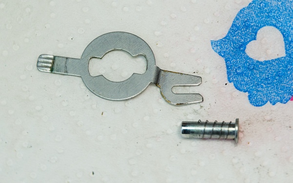
Below are the parts that come out during this process: the fork, a washer, a spring, and a few oddly shaped metal discs.
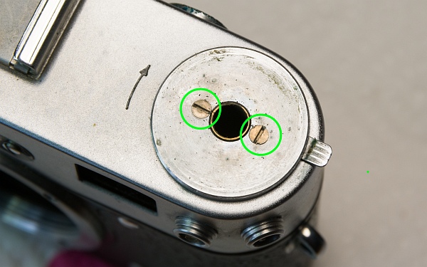
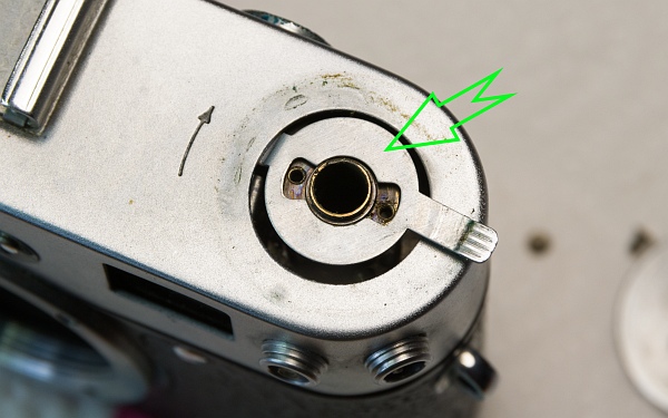
At the very bottom: Now loosen the two screws on the cover plate that hold the diopter adjustment lever in place. The lever can be easily pulled out.
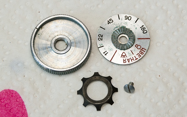
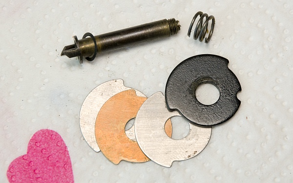
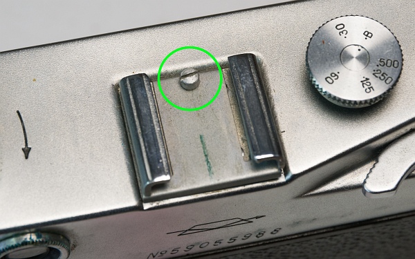
Now let's remove the screw in the accessory shoe and take out the small metal plate. The accessory shoe itself is held in place by 4 screws and should be removed later, since it is secured on the inside by a threaded plate.
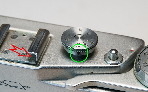
Remove the small set screw in the speed dial and pull it straight up to remove it. Note the bent accessory shoe (red arrow)!
1.3. Remove the tension lever.
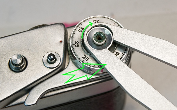
First, use a suitable tool to unscrew the collar around the shutter release clockwise (!). The collar may be very tight. Cock the shutter first (left).
Then remove the film counter disc and the spring washer (bottom left).
Using a wrench, remove the brass-colored disc with the two slots, also turning it clockwise (bottom).
Underneath is another disc with two holes. Unscrew this counterclockwise using a spanner (bottom left).
Now you can remove the three screws and then take off the chrome-plated housing of the film counter (bottom).
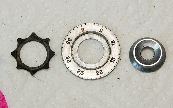
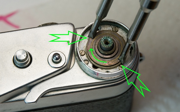
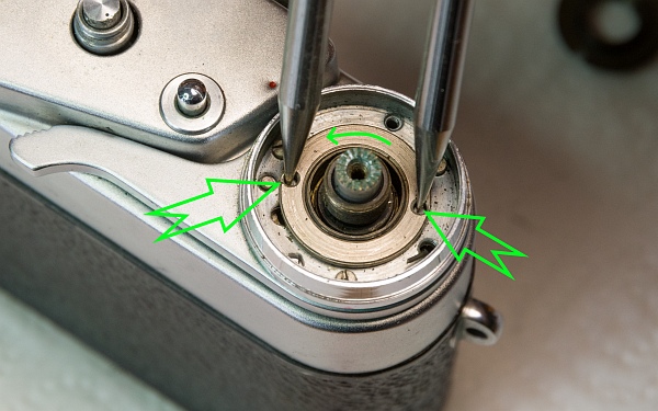
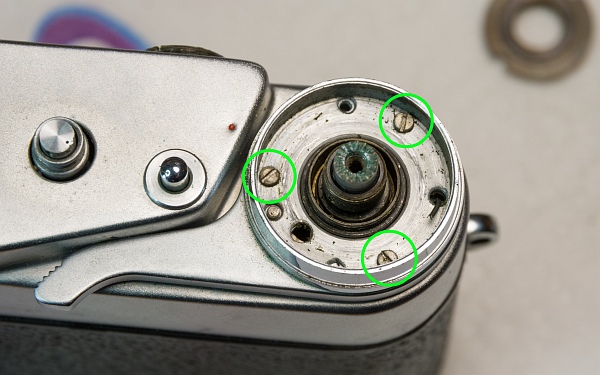
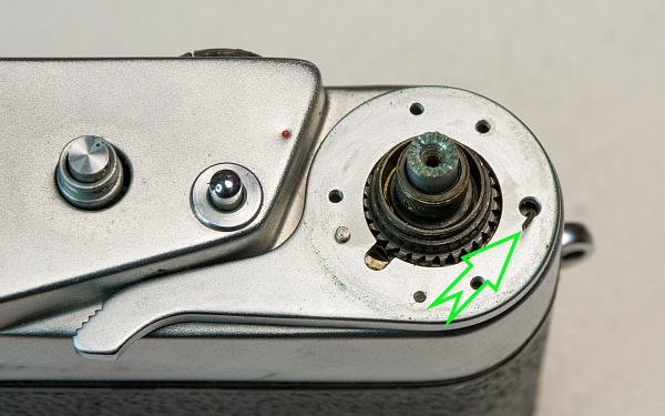
The tension lever is now exposed; unhook it from the spring on the right and remove it. As you do this, the spring - which returns the tension lever to its original position after tensioning - uncoils (left).
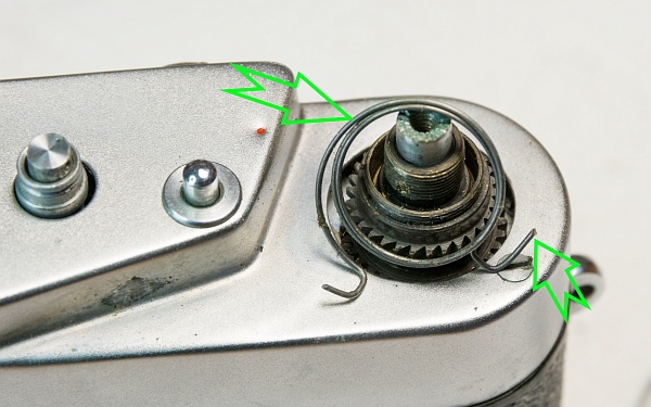
The uncoiled tension spring. It is secured on the right behind the long housing screw. The left end is the part that was just unhooked from the tension lever. Remove the spring (bottom left).
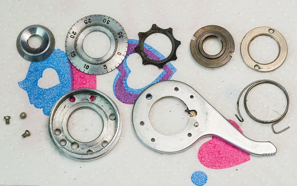
All parts of the disassembled tension lever (below).
Now we’ll remove the long housing screw and then take off the cover. The small rewinding release button will pop out as you do this (at the very bottom).
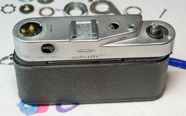
On the left are the diopter adjustment lever and the small knob for releasing the rewind mechanism.
2. Remove the housing
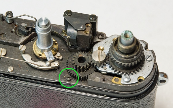
To access the gears for cleaning, we need to remove the housing.
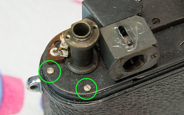
First, loosen the 4 marked screws on the top (left and bottom).
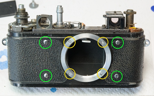
Next, remove the 4 marked screws on the front and the 4 yellow-marked screws on the lens mount. As usual, you’ll find several wax paper shims underneath to adjust the correct flange focal distance. Then you can slide the housing off (bottom left).
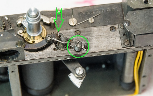
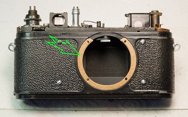
Now you can also see why the camera won’t fire when no lens is attached: The inner rangefinder arm swings back so far that it collides with the shutter control mechanism. Therefore, remove the screw in the circle and take off the spring so that the arm isn’t in the way during testing (bottom left).

3. Cleaning, Lubrication, and Assembly
3.1. Brush the teeth.
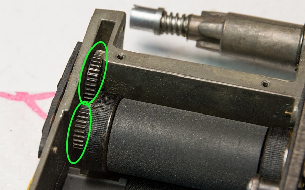
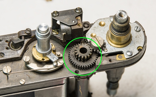
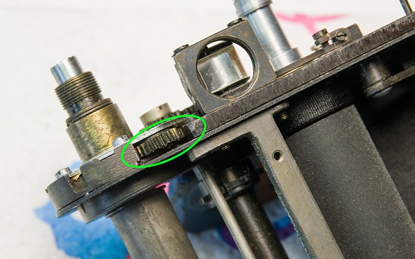
As usual, clean all the gears of the winding mechanism on the underside, as well as the two large gears of the shutter at the bottom (left).
The large double gear of the winding lever can be easily removed and cleaned. Reattach it temporarily to wind the camera and clean the other gears.
Clean all the marked gears while winding the camera with the double gear to reach all the teeth (left and bottom).
Now lubricate all the gears with a bit of oil (at the bottom of the shutter) and a bit of grease (on the winding mechanism at the top).
After cleaning and re-lubricating, the shutter should operate reasonably smoothly again. Once the camera is reassembled, the shutter speeds can be fine-tuned as usual using the shutter tension screws.
Of course, we also clean and polish all chrome parts and clean the viewfinder lenses and eyepieces.
3.2. Reattach the housing.
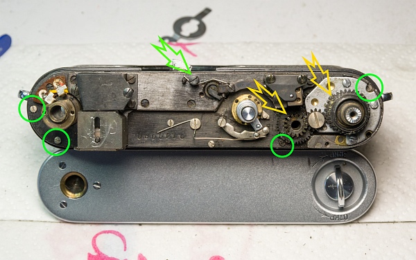
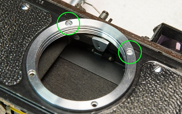
Slide the housing back on and secure it at the top with the 4 screws marked by the green circles. Reattach the rangefinder spring (green arrow). Replace the double gear and grease the two gears (yellow arrows) (left).
We screw the four front housing screws back in and replace the wax paper washers exactly as we found them (bottom left).
Then, reattach the lens mount using the two threaded plates (bottom).
3.3. Put the cover back on.
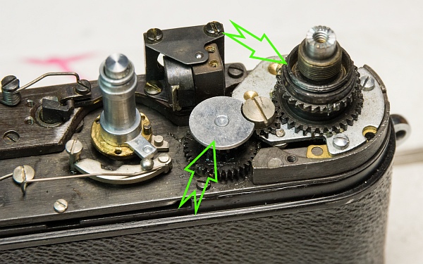
First, put the double gear back in place (if you haven't already) and then reinsert the rewind release plate into the hole in the gear on the left (left side).
Then position the rewind release button, along with the spring, in the center of the plate (bottom left).
Now replace the cover from the right, making sure that the rewind release button protrudes at the point marked with an arrow. This can be a bit fiddly (below).
With the cover not yet fully closed, insert the diopter adjustment lever so that the fork of the lever (already under the cover here) snaps into the pin of the movable diopter correction lens. Then place the cover on completely. Test whether the lens moves when you operate the lever (bottom left).
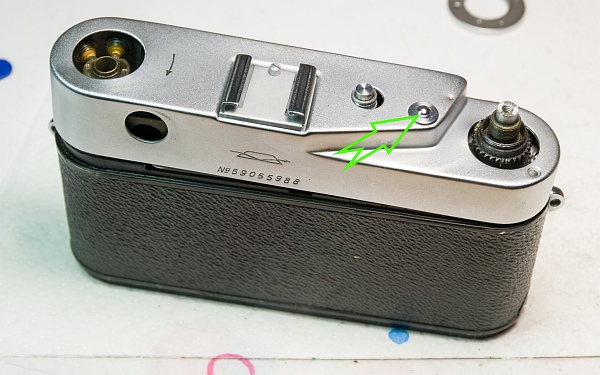
Last but not least, we screw the long case screw back in (bottom).
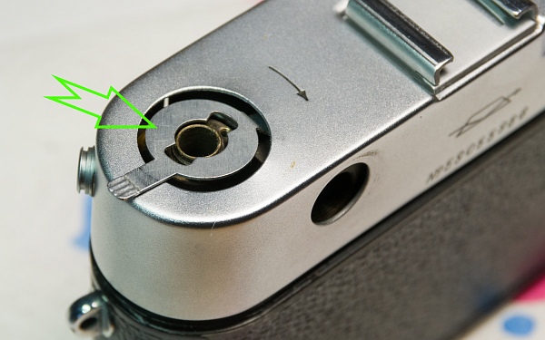
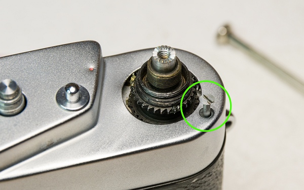
3.4. Install the rewind crank.
First, replace the diopter adjustment cover. It has a notch for the lever.
It is secured with 2 screws. Check to make sure the diopter adjustment works properly.
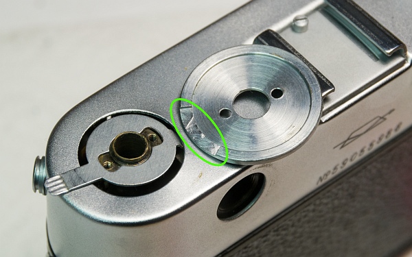
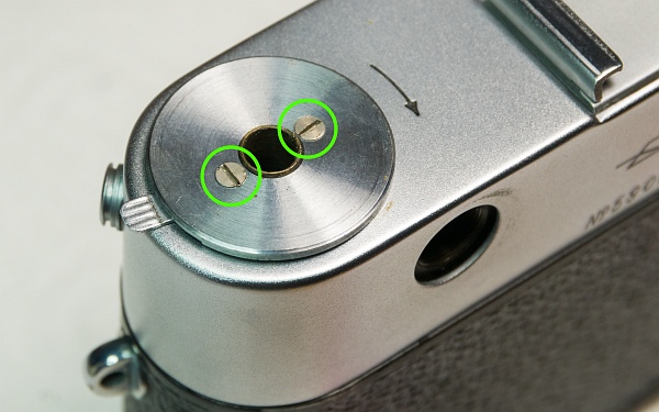
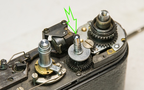
Place the washer and the spring onto the fork of the rewind crank.
Put the oddly shaped metal washers you removed earlier back into the housing and insert the fork through the hole.
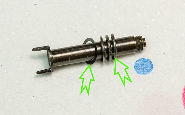
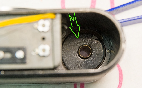
Hold the fork firmly in place and screw on the rewind crank knob.
Now insert the spring washer and the film mark disc, and secure them with the corresponding screw.
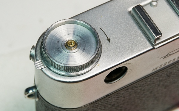
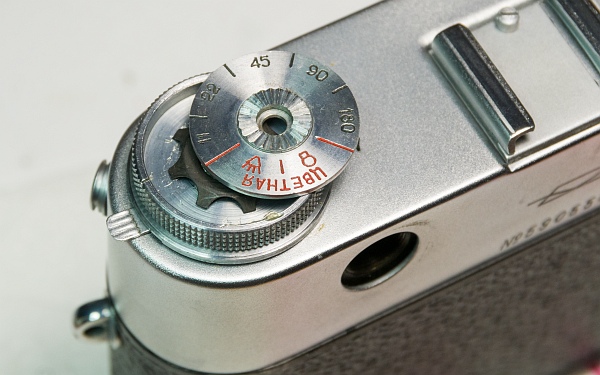
3.5. Install the tension lever.
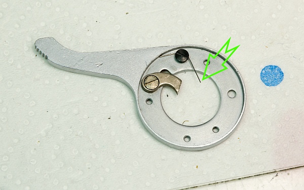
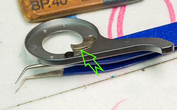
Before installing the tension lever, the pawl on the underside must be properly reinstalled. The small spring must be positioned in the notch of the pawl (left and bottom left).
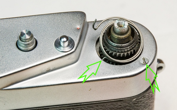
Reinsert the tension spring: The longer, bent hook (left arrow) must be hooked behind the long screw on the cover (right arrow) (bottom).
Now it gets a little more complicated: Take the tension lever and hook it into the shorter end of the tension spring. Then turn the tension lever into the correct position, making sure that the pawl engages with the upper gear of the double gear (bottom left).
Now take the chrome-plated housing of the film counter disc, hook it onto the tension spring as well, and position it as shown (at the very bottom).
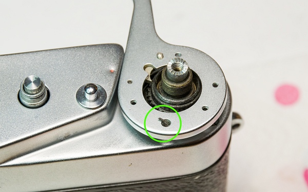
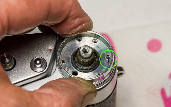
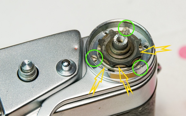
Secure the housing with the 3 screws (green circles), screw the two discs back on (first the one with the two holes, then the one with the two slots - note the left-hand thread), and place the spring washer on top.
Then reinsert the film counter disc and screw the collar around the shutter release (left-hand thread) back on tightly.

3.6. Adjust the rangefinder.
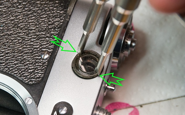
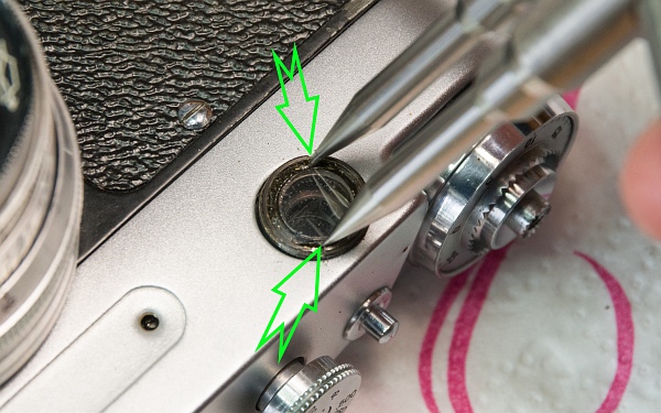
Screw the front eyepiece back in using a spanner. The rear eyepiece only needs to be screwed in by hand (left).
You can now adjust the vertical offset of the rangefinder using a spanner by slightly rotating the eyepiece lens (bottom left).
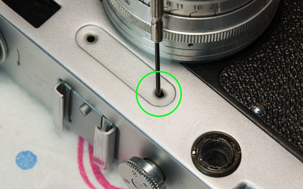
The adjustment screw for the horizontal offset is located under the nameplate (below).
4. Result
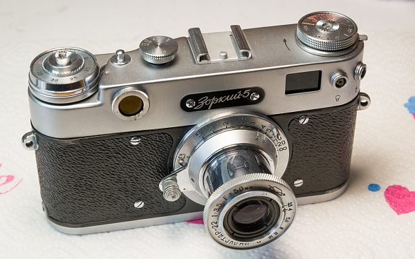
The result is really quite impressive!